| Parameters(26) | Default | Remark |
| Tth0 |
25 |
Initial temperature of the heat sink |
| CthJ |
1m |
Thermal Junction capacitance |
| RthJC |
0.8 |
Thermal resistance Junction to Case |
| LG |
5nH |
|
| LS |
12nH |
|
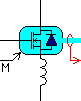
| M |
0.5 |
|
| RD |
190m |
On state Drain-Source Resistance |
| RG |
10 |
Internal Gate Resistance [Ohm] |
| VJ |
1 |
|
| VTO |
3 |
|
| LD |
10n |
|
| CDS |
730pF |
|
| CGD |
50pF |
|
| CGS |
2350pF |
|
| KP |
6.4 |
|
| FC |
0.5 |
|
| TT |
0 |
Forward storage time (Transit Time) |
| Trr |
0 |
Reverse Recovery Time [s] |
| tau_rr |
0 |
Time delay for the reverse recovery current |
| Rs |
1m |
Series parasitic resistance of the diode |
| Qrr |
0 |
Reverse Recovery Charge[C] |
| N |
1.5 |
Emission Coefficient |
| Is |
1e-12 |
Saturation Current |
| IF |
0 |
Forward Current before reverse recovery [A] |
| DIFDT |
0 |
Slope of reverse recovery current [A/s] |
| BV |
650 |
Diode Reverse Break down voltage[V] |