| IR | IS | IT | SENSOR | ||
| L1 | 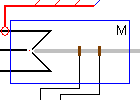
| M | |||
| L2 | SHAFT | ||||
| L3 | |||||
| EA | EB | ||||
SynE - Synchronous Machine with excitation winding |
Back to the index Back to the top of index |
| IR | IS | IT | SENSOR | ||
| L1 |
| M | |||
| L2 | SHAFT | ||||
| L3 | |||||
| EA | EB | ||||
| Connections(11) | Position | Remark |
| SHAFT | Right | Mechanical Rotor Shaft |
| SENSOR | Top | Monitor the internal variables like currents, Field and position |
| M | Right | Connection to a .Model parameter database |
| L3 | Left | Stator terminal phase T |
| L2 | Left | Stator terminal phase S |
| L1 | Left | Stator terminal phase R |
| IT | Top | Stator current phase T |
| IS | Top | Stator current phase S |
| IR | Top | Stator current phase R |
| EB | Bottom | Excitation winding phase b |
| EA | Bottom | Excitation winding phase a |
| Parameters(9) | Default | Remark |
| Lq[H] | 0.15m | Stator quadrature axis inductance in [H] |
| Ld[H] | 0.15m | Stator direct axis inductance in [H] |
| Rs[ohm] | 3 | Stator Series Resistance per phase in [ohm] |
| Rexcitation[ohm] | 4 | Excitation field winding resistance in [ohm] |
| Lexcitation[H] | 10m | Excitation field winding inductance in [H] |
| Lmutual[H] | 0.1m | Mutual inductance between the excitation winding Lexcitation and the direct axis inductance Ld in [H] |
| Friction[Nm/Rad/s] | 1u | Bearing friction of the rotor in [Nm/Rads/s] |
| J[Kgm2] | 1m | Rotor Inertia in [Kgm2] |
| PolePair[.] | 2 | Number of pole pairs [#] |
| Function | ||
| Status | Standard | |
| Select from | Components\Library\ElectricalMachines\Synchronous | |
 |
Back to the index Back to the top of index |