| SENSOR | ||
| L1 | 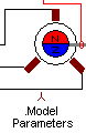
| SHAFT |
| L2 | ||
| L3 | ||
| M |
pmsm - PMSM Salient pole |
Back to the index Back to the top of index |
| SENSOR | ||
| L1 |
| SHAFT |
| L2 | ||
| L3 | ||
| M |
| Connections(6) | Position | Remark |
| SHAFT | Right | |
| SENSOR | Top | |
| M | Bottom | |
| L3 | Left | |
| L2 | Left | |
| L1 | Left |
| Parameters(7) | Default | Remark |
| Rs[Ohm] | 10m | Stator Series Resistance |
| Ld[H] | 1m | Stator direct axis inductance in [H] |
| Lq[H] | 1m | Stator quadrature axis inductance in [H] |
| Ke[Vpeak/Rad/s]=[Nm/A]=[Wb] | 0.1 | Flux induced in the stator windings (Wb) by the rotor permanent magnets |
| PolePair[.] | 10 | Number of pole pairs [#] |
| Inertia[Kgm2] | 1m | Rotor Inertia in [Kgm2] |
| Friction[Nm/Rad/s] | 1u | Bearing friction of the rotor in [Nm/Rad/s] |
| Function | Permanent magnet synchronous machine with salient poles. Use this model for IPM and buried magnet rotors | |
| Special | The value of Ld and Lq can be specified independently. | |
| Status | Standard | |
| Select from | Components\Library\ElectricalMachines\Synchronous | |
 |
Back to the index Back to the top of index |