| SENSOR | ||||||
| L1 | 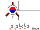
| SHAFT | ||||
| L2 | ||||||
| L3 | ||||||
| ID | IQ | LD | LQ | M | ||
PMSMsaturation - Permanent Magnet Synchronous Machine with Saturation |
Back to the index Back to the top of index |
| SENSOR | ||||||
| L1 |
| SHAFT | ||||
| L2 | ||||||
| L3 | ||||||
| ID | IQ | LD | LQ | M | ||
| Connections(10) | Position | Remark |
| SHAFT | Right | |
| SENSOR | Top | |
| M | Bottom | |
| LQ | Bottom | Lq[H] |
| LD | Bottom | Ld[H] |
| L3 | Left | |
| L2 | Left | |
| L1 | Left | |
| IQ | Bottom | PMSM Quadrature axis current iq [A] |
| ID | Bottom | PMSM Direct axis current id [A] |
| Parameters(7) | Default | Remark |
| Rs[ohm] | 10m | Stator Series Resistance |
| Ld[H] | 10m | Stator direct axis inductance offset value in [H] |
| Lq[H] | 10m | Stator quadrature axis inductance offset value in [H] |
| Ke[Vpeak/Rad/s]=[Nm/A]=[Wb] | 0.15 | Flux induced in the stator windings (Wb) by the rotor permanent magnets, also known as back emf constant or torque constant |
| PolePairs[.] | 4 | /number of pole pairs [#] |
| J[Kgm2] | 1m | Rotor Inertia in [Kgm2] |
| Friction[Nm/Rad/s] | 1u | Bearing friction of the rotor in [Nm/Rad/s] |
| Function | The values of Ld and Lq are input on the bottom side of the block and can be made dependent on the currents Id and Iq | |
| Special | The offset values for Ld and Lq are added to the varaible inductance values that are input at the bottom of the model | |
| Status | Standard | |
| Select from | Components\Library\ElectricalMachines\Synchronous | |
 |
Back to the index Back to the top of index |