| TOP | |||
| LEFT | 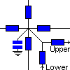
| RIGHT | |
| ZUP | |||
| BOTTOM | ZDOWN | ||
Heatsink_3D - Heat sink 3D |
Back to the index Back to the top of index |
| TOP | |||
| LEFT |
| RIGHT | |
| ZUP | |||
| BOTTOM | ZDOWN | ||
| Connections(6) | Position | Remark |
| ZUP | Right | Upper connection |
| ZDOWN | Bottom | Lower Connection |
| TOP | Top | |
| RIGHT | Right | |
| LEFT | Left | Thermal node |
| BOTTOM | Bottom |
| Parameters(4) | Default | Remark |
| Rthxy | 1 | Thermal resistance for the 2d Layer in xy direction |
| Cth | 1 | Thermal capacitance |
| InitialTemperature | 25 | Initial temperature of the heat sink |
| Rthz | 1 | Thermal resistance in the z direction between Upper and Lower connection |
| Function | Three-dimensional heat sink The parameters Cth and Rth are from the datasheet. | |
| Special | Depending on the temperature the heat sink is colored, where the color level is defined by the voltage level in the animation properties dialog box. The 3D blocks are first connected in a 2D grid, to form a single layer. Individual layers are connected by giving the [up] node from one layer the same labe las the [down] node from the underlaying layer. |
|
| Note | Specify the initial temperature for the thermal capacitor. | |
| Status | Standard | |
| Select from | Components\Library\Thermal\Heatsink | |
 |
Back to the index Back to the top of index |