| G1H | G1L | G2H | G2L | G3H | G3L | ||
| ANGLE | 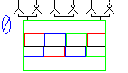
| RA | |||||
| RB | |||||||
SixStep - Gate Control BLDCM |
Back to the index Back to the top of index |
| G1H | G1L | G2H | G2L | G3H | G3L | ||
| ANGLE |
| RA | |||||
| RB | |||||||
| Connections(9) | Position | Remark |
| RB | Right | Controller vector position b |
| RA | Right | Controller vector position a |
| G3L | Top | |
| G3H | Top | |
| G2L | Top | |
| G2H | Top | |
| G1L | Top | |
| G1H | Top | |
| ANGLE | Left | Connect the measured rotor position here |
| Parameters(0) | Default | Remark |
| Function | Gate control for the BLDCM + inverter | |
| Special | Feed the rotor position to input Angle. The outputs Ra and Rb can be connected to a scope to see the rotor position controller output as a vector. Connect the outputs G1H, G2 H and G3H to the high side Mosfets/IBGTs in the inverter. Connect the outputs G1L, G2 L and G3L to the low side Mosfets/IBGTs in the inverter. | |
| Status | Standard | |
| Select from | Components\Library\PowerConverters\Inverters3phase | |
 |
Back to the index Back to the top of index |