| TEL | ||
| R | 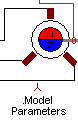
| ROTOR |
| S | ||
| T | ||
| M |
PMSM - Permanent Magnet Synchronous Machine |
Back to the index Back to the top of index |
| TEL | ||
| R |
| ROTOR |
| S | ||
| T | ||
| M |
| Connections(6) | Position | Remark |
| TEL | Top | |
| T | Left | |
| S | Left | |
| ROTOR | Right | |
| R | Left | |
| M | Bottom |
| Parameters(6) | Default | Remark |
| JR[Kgm2]] | 100m | Rotor inertia |
| LS[H] | 15m | Winding inductance per phase |
| RS[ohm] | 10m | Winding resistance per phase |
| Friction[Nm/Rad/s] | 1m | Friction of the bearing in Nm per Rad/s |
| Ke[Vpeak/(Rad/s)]]=[Nm/A] | 1 | Torque / back emf constant in [Vpeak/Rad/s] or [Nm/A] |
| polepair[.] | 1 | Number of pole pairs |
| Function | Permanent Magnet Synchronous Machine with sinusoidal back emf | |
| Note | The inductance and resistance are given per phase. The resistance and inductance between two terminals equals 2*Rs and 2*Ls | |
| Status | Standard | |
| Select from | Components\Library\ElectricalMachines\PMSM | |
 |
Back to the index Back to the top of index |