| TEL | ||||
| R | 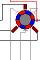
| ROTOR | ||
| S | ||||
| T | ||||
| H1 | H2 | H3 | ||
BrushlessDC - Brushless DC Permanent Magnet Machine |
Back to the index Back to the top of index |
| TEL | ||||
| R |
| ROTOR | ||
| S | ||||
| T | ||||
| H1 | H2 | H3 | ||
| Connections(8) | Position | Remark |
| TEL | Top | |
| T | Left | |
| S | Left | |
| ROTOR | Right | |
| R | Left | |
| H3 | Bottom | Hall Sensor input T |
| H2 | Bottom | Hall sensor input S |
| H1 | Bottom | Hall Sensor input R |
| Parameters(8) | Default | Remark |
| JR[Kgm2] | 1m | |
| LS_Phase(including LM) | 1m | |
| RS_phase | 3 | |
| f[Nm/Rad] | 1m | |
| Ke[Vpeak/Rad] | 1 | |
| PolePairs | 1 | Number of Pole Pairs |
| AngularPolePitch[Rad] | 2.0943951 | Angular Pole pitch of the magnets on the Rotor. The angular pole pitch is limited to pi/(Number of pole pairs) |
| AngularConductionPitch[Rad] | 2.0943951 | Angular width of the magnet for the hall sensor |
| Function | Permanent Magnet Brushless DC Machine with rectangular back emf | |
| Note | The inductance and resistance are given per phase. The resistance and inductance between two terminals equals 2*Rs and 2*Ls | |
| Status | Standard | |
| Select from | Components\Library\ElectricalMachines\Brushless | |
 |
Back to the index Back to the top of index |