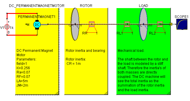
To model mechanical systems, basic mechanical models have been included in Caspoc. There are basic models for Translational and Rotational drives, such as Speed, Force and Torque sources. Using Masses, Springs, and Bearings, a basic mechanical system can be constructed. The basic mechanical components are can be found under Component/Circuit/Translational and Component/Circuit/Rotational. During animation the angular position in a Rotational drive is animated by a line along the shaft and an indicator on rotating masses.

The objective is to model simple mechanical structures that are either rotating or translating and are connected to the shaft of an electrical machine. More elaborate models for a gearbox, clutch, couplings, etc can be found in the library.

A mechanical structure is constructed in the same way as an electrical circuit is constructed. The major difference is that no ground node is required. From the shaft of an electrical machine, you can immediately draw a shaft(without any mass) and connect it to a spring, inertia or bearing. Multiple inertias can directly be placed next to each other to model a stiff shaft with mass.

In the above figure the shaft between the rotor and the load is modeled by a stiff shaft. Therefore the inertia's of both masses are directly coupled. The DC machine will see the total inertia as the summation of the rotor inertia and the load inertia. The bearings model a linear friction of the shaft.
Connect the shaft to a scope to view the angular speed for rotating systems or the speed for translating systems. Drag and dropping the input of the scope over components such as an inertia, displays the torque or force in that component.