Switched Reluctance Motors
 |
A switched reluctance or variable reluctance motor does not contain any
permanent magnets. The stator is similar to a brushless dc motor. However,
the rotor consists only of iron laminates. The iron rotor is attracted to
the energized stator pole. The polarity of the stator pole does not
matter. Torque is produced as a result of the attraction between the
electromagnet and the iron rotor.
The rotor forms a magnetic circuit with the energized stator pole. The
reluctance of a magnetic circuit is the magnetic equivalent to the
resistance of a electric circuit. The reluctance of the magnetic circuit
decreases as the rotor aligns with the stator pole. When the rotor is
aligned with the stator the gap between the rotor and stator is very small.
At this point the reluctance is at a minimum. This is where the name
'Switched Reluctance' comes from.
The inductance of the energized winding also varies as the rotor
rotates. When the rotor is out of alignment, the inductance is very low,
and the current will increase rapidly. When the rotor is aligned with the
stator, the inductance will be very large and the slope decreases. This is
one of the difficulties in driving a switched reluctance
motor. |
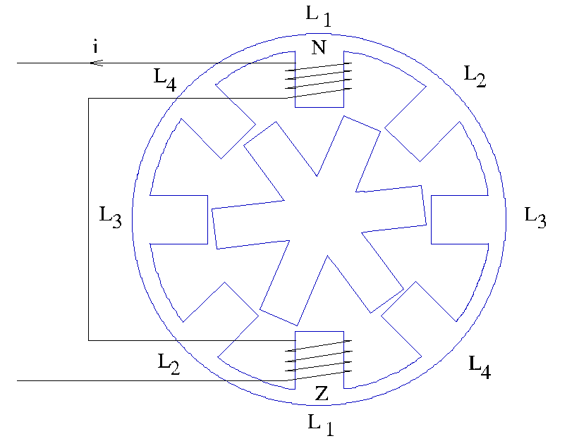
The model of a Switched Reluctance Machine (SRM) is a highly non-linear model, because the stator inductance is dependent on the rotor position. There are more stator poles than rotor poles and for the various combinations of stator and rotor poles, different models are required, because the number of stator poles indicates the number of stator inductance's connected to the electric circuit. For example, a SRM 8/6 has 4 stator inductors that are connected the inverter, while a SRM 6/4 only has 3.
The construction of a SRM 8/6 is given in the figure below.

The parameters of the SRM are mainly geometric parameters, the maximum and minimum stator inductance and the torque constant. The stator inductance varies from a minimum to a maximum value, depending on the alignment of the rotor and stator tooth.
Suppose a SRM has Nr rotor poles, the stator inductance is a periodic function of the rotor position with a periodicity of 2π/Nr radians.

The stator inductance varies between Lmin and Lmax. When the stator and rotor poles are aligned, the stator inductance has its maximum value Lmax. When there is no rotor pole aligned with the stator pole, the stator inductance has its minimum function Lmin.

The rotor position is given by the angle α, which is positive in anti-clockwise direction. The rotor position α is 0 when the rotor pole starts to align with the stator pole. In the above figure the rotor position angle α is negative or less than 2π. In the figure below the stator inductance dependency on the rotor position is shown.

Non-linear mathematical relations model the stator inductance of the SRM. The value of the inductance per phase is depending on the position of the rotor is:
| Rotor position | Stator inductance |
| α<0 | Lmin |
| 0<α<βs | Lmin+K*α |
| βs<α<βr | Lmax |
| βs<α<βs+βr |
Lmin-K*(α-(βs+βr)) |
where:
K=(Lmax-Lmin)/βs
and α is the angle between the stator and the rotor.
The torque of the SRM is given in the figure below

and is dependent on the stator current and the torque constant
TSRM=½K*i2
The torque produced by the SRM is coupled with the model describing the dynamic behavior of the mechanics of the drive.
The torque is only produced when the rotor pole has to align with the stator pole. Therefore a controller has to be used that knows the position of the rotor. The model in Caspoc has a control node that is set to 1 whenever the rotor pole starts to align with a stator pole. These nodes are on the topside of the library models of the SRM. The control node for the first stator inductor is given below

The mechanical shaft is modeled by a rigid shaft model. Most machine models have internal parameters for modeling the inertia and friction of the shaft. The SRM can either run without load or can be connected to a mechanical rotational model. Use the models from components/circuit/rotational and from the various mechanical libraries for modeling the mechanical model.
The resulting angular speed is used to calculate the angle between the stator and the rotor.
Depending on the position of the rotor the power converter has to be controlled such that a rotating stator field is generated.
© Simulation Research, www.caspoc.com


