| SENSOR | |||||
| L1 | 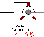
| SHAFT | |||
| L2 | |||||
| L3 | |||||
| LM | M | RR | RS | ||
IMwye_Saturation - Induction Machine with saturation |
Back to the index Back to the top of index |
| SENSOR | |||||
| L1 |
| SHAFT | |||
| L2 | |||||
| L3 | |||||
| LM | M | RR | RS | ||
| Connections(9) | Position | Remark |
| SHAFT | Right | |
| SENSOR | Top | |
| RS | Bottom | Stator resistance |
| RR | Bottom | Rotor resistance |
| M | Bottom | |
| LM | Bottom | Magnetizing inductance |
| L3 | Left | |
| L2 | Left | |
| L1 | Left |
| Parameters(5) | Default | Remark |
| Lr | 0.6m | Rotor leakage inductance |
| Ls | 0.6m | Stator leakage inductance |
| p | 2 | pole pairs |
| J | 1m | Rotor Inertia |
| f | 1u | Friction of the rotor |
| Function | Induction machine model based on the stator fixed coordinate system. | |
| Status | Standard | |
| Select from | Components\Library\ElectricalMachines\IM | |
 |
Back to the index Back to the top of index |