| I1 | I2 | I3 | TEL | ||
| M | 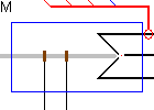
| R | |||
| ROTOR | S | ||||
| T | |||||
| FA | FB | ||||
Alternator - Synchronous Generator |
Back to the index Back to the top of index |
| I1 | I2 | I3 | TEL | ||
| M |
| R | |||
| ROTOR | S | ||||
| T | |||||
| FA | FB | ||||
| Connections(11) | Position | Remark |
| TEL | Top | Sensor connection |
| T | Right | Stator terminal phase T |
| S | Right | Stator terminal phase s |
| ROTOR | Left | Mechanical shaft |
| R | Right | Stator terminal phase R |
| M | Left | Connection to the .MODEL database |
| I3 | Top | Stator current phase T |
| I2 | Top | Stator current phase S |
| I1 | Top | Stator current phase r |
| FB | Bottom | Field winding connection b |
| FA | Bottom | Field winding connection a |
| Parameters(8) | Default | Remark |
| JR | 100m | |
| LS | 15m | |
| RS | 3 | |
| f | 1m | |
| RE | 4 | Excitation winding resistance |
| LE | 1m | Excitation winding inductance |
| Ke | 1 | |
| Kmax | 1 | Maximum Excitation field |
| Function | Synchronous Generator with sinusoidal back emf | |
| Note | The inductance and resistance are given per phase. The resistance and inductance between two terminals equals 2*Rs and 2*Ls | |
| Status | Standard | |
| Select from | Components\Library\ElectricalMachines\Alternator | |
 |
Back to the index Back to the top of index |